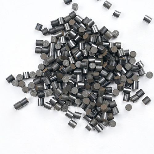
How to Select an HTS Catalyst for Ammonia and Hydrogen Plants
Select a high-temperature shift (HTS) catalyst by evaluating the inlet gas composition, steam conditions, temperature, throughput, reactor and bed configuration, together with CO conversion, pressure drop and mechanical stability over the intended operating cycle. A grade designation, composition figure or particle size provides only part of the information. The final recommendation should address the specific plant conditions and acceptance requirements. This guide is for process, equipment, purchasing and engineering teams working on ammonia and hydrogen plants. It explains how to assess technical suitability. Product operating limits, loading and activation requirements must follow the approved technical documents and project-specific technical proposal. The water-gas shift (WGS) reaction converts carbon monoxide and steam into carbon dioxide and hydrogen: CO + H₂O ⇌ CO₂ + H₂ The forward reaction is exothermic. Lower temperatures favour a lower equilibrium CO concentration, but reaction kinetics and catalyst activity must also support the required throughput. A catalyst changes the reaction rate; it does not change thermodynamic equilibrium under the same conditions. Selection therefore requires a combined assessment of kinetics, equilibrium and temperature changes. Neither a higher temperature nor higher activity alone determines the outlet CO concentration. Start by confirming three questions: Conventional HTS, LTS, medium-temperature shift and sour gas shift use different catalyst systems and operating conditions. They cannot be treated as interchangeable simply because all are called shift catalysts. Where the duty is syngas composition adjustment for methanol synthesis, establish the required extent of shift from that process's syngas targets. Conventional iron-chromium HTS catalysts generally contain iron oxide as the main component, with promoters such as chromium oxide providing structural stability. Some formulations also contain copper promoters. During the specified activation procedure, Fe₂O₃ in an oxidic product is converted to a working active phase based on Fe₃O₄. Further reduction to metallic iron is not the normal activation objective. Commercial HTS technologies also include non-iron, chromium-free systems. Confirm the composition, activation requirements and operating window for the specific product rather than treating every HTS catalyst as the same formulation. These categories explain technical differences; they are not a grade replacement table. In particular, some sulfur tolerance in a conventional HTS catalyst does not establish suitability for any sour gas shift process. Prepare a common technical data sheet with separate entries for current normal operation, expected variations and planned capacity increases. Ask the supplier to identify which set of conditions is used for each performance prediction. The inlet gas means the process gas entering the HTS reactor, not an analysis of the original natural gas or other raw feedstock. Feedstock origin is useful background, but it cannot replace the HTS inlet composition. For the purchasing documents to assemble alongside these technical inputs, see the HTS catalyst enquiry preparation checklist. The steam-to-dry-gas ratio (S/DG) can be expressed using molar flows at the same inlet location: S/DG = steam molar flow ÷ process-gas molar flow excluding water vapour For the steam-to-carbon ratio (S/C), the denominator is the defined carbon quantity in the feedstock or gas stream. Specify the calculation basis and process location. The two ratios cannot be compared simply by their numerical values. For conventional iron-based HTS catalysts, certain low-steam, strongly reducing conditions can cause over-reduction, loss of strength and side reactions. Establish the minimum permissible value for the formulation, gas composition and project conditions. A limit for one grade or plant is not a universal HTS standard. Gas hourly space velocity (GHSV), when defined on a dry-gas basis, is commonly expressed as: GHSV = dry-gas volumetric flow at specified reference conditions (m³/h) ÷ bulk loaded catalyst volume (m³) The unit is h⁻¹. State whether the flow includes steam, its reference temperature and pressure, and the catalyst volume used as the denominator. Do not directly compare space velocities calculated on different bases. An inlet temperature range, maximum allowable temperature and short-term tolerance describe different requirements. A maximum temperature limit is not a recommended normal inlet temperature. Ask the supplier to explain: High fresh-catalyst activity and compliance throughout the operating cycle are separate evaluation criteria. Review long-term activity, thermal stability and mechanical integrity within the same technical proposal. When comparing outlet CO, align the inlet composition, steam conditions, temperature, flow, loaded volume and catalyst operating age. A low CO result from another plant may be a useful reference, but it does not automatically become a performance guarantee for this plant. Distinguish three types of CO figures: Outlet CO concentration is not the same as CO conversion. Conversion requires a material balance using CO molar flow rates; it should not be calculated as a simple difference between dry-basis inlet and outlet concentrations. For technical comparisons, ask the supplier to explain the approach to equilibrium, prediction method, test conditions and scope of applicability. The evaluation should show the conditions behind each result, rather than present only the most favourable number. Particle size, shape, bed voidage and loading method affect catalyst bed performance. A hydraulic review must also include gas properties, actual flow, bed height and reactor internals. Establish whether the measured pressure drop is across the catalyst bed alone or across the reactor, including support layers, collectors and other internals. Replacing the catalyst may not resolve every source of flow resistance. Single-particle crush strength, bulk crushing strength and results from different test methods cannot be ranked by numerical value alone. Review mechanical properties together with the test method and service conditions. For an initial purchasing estimate: Net catalyst mass (kg) ≈ catalyst loading volume (m³) × corresponding bulk density (kg/m³) Exclude support or inert materials purchased separately from the catalyst volume. Use a density appropriate to the product, particles and loading basis, and confirm estimation tolerances and spare-material requirements. At the same volume, lower bulk density generally means a lower catalyst mass. Total purchasing cost still depends on unit price, actual quantity and service scope, while technical performance requires a separate assessment. Neither price per tonne nor density alone establishes the better option. Rising outlet CO, increasing pressure drop and a shorter operating cycle can have different causes. Before selecting a replacement, review gas analyses, temperature and pressure drop trends, and inspection records to identify the main plant limitation. Do not directly apply copper-based LTS impurity requirements to conventional HTS service. Equally, do not extend one product's impurity tolerance to every shift catalyst. Ask the supplier to respond to the actual process gas. Matching particle dimensions and a similar chemical composition are insufficient for a replacement assessment. Also review: Activation heating, reducing-gas composition, steam conditions and shutdown protection belong in the approved product- and plant-specific operating procedures. This selection guide does not provide a start-up sequence for direct operational use. An HTS catalyst recommendation should address at least the following: The final choice also needs to reflect the planned operating cycle, turnaround schedule, supply and service conditions. Longer-term cost comparisons should state assumptions for price, energy use, capacity and downtime, rather than treating a saving reported for one project as a universal benefit. No. Conventional iron-chromium HTS catalysts are based on an iron oxide system, with an operating active phase principally associated with Fe₃O₄. Commercial non-iron systems also exist. Check the approved technical data for the specific grade. No. Review inlet and bed temperatures, allowable conditions and long-term performance separately. A maximum temperature figure does not establish that a product will meet the target CO under every operating condition. Assess the limitations of the whole plant. Catalyst, support layers and internals all affect flow resistance; compressors, heat duties and other equipment can also constrain output. A project-specific calculation is needed before claiming a capacity increase. Establish whether it is an operating record, a performance prediction or a contractual commitment. Then compare inlet gas, load, temperature, loading and end-of-run requirements. Report time already in service separately from the predicted total life. For an HTS catalyst assessment, provide the available inlet process-gas analysis, temperatures and pressure, gas and steam flows, reactor or loading drawings, and target CO and operating cycle. If information is incomplete, start with the current specification and project requirements, then identify what is still needed for the assessment. See the SYAMCAT high-temperature shift catalyst product information, or use the contact page to discuss product selection, supply scope and technical documentation.1. Confirm the Process Route and Shift Duty
2. Distinguish the Supplied Composition from the Active Phase
Catalyst system or description What it means for selection What to confirm Conventional iron-chromium systems and improved formulations Iron oxides and structural or activity promoters contribute to performance. Total iron content alone is not a complete performance assessment. Supply state, activation requirements, applicable steam conditions, activity and mechanical stability. Non-iron, chromium-free HTS products Commercial alternatives to conventional iron-chromium formulations exist. Compatibility with the existing process, loading and activation arrangements, and any associated modifications. Low-hexavalent-chromium or essentially hexavalent-chromium-free products This describes a specific chromium species; it does not mean the product contains no total chromium. The distinction between total chromium and Cr(VI), the analytical basis and the relevant product documents. Sour gas shift products Different active systems, including sulfided cobalt-molybdenum catalysts, can be used for the corresponding sulfur-containing process gas. Sulfur conditions, activation or sulfiding state, operating window and process requirements, assessed separately. 3. Separate Design Conditions, Actual Operation and Future Targets
Required input Information to provide Why it matters HTS inlet process gas CO, CO₂, H₂, CH₄, N₂ and other relevant components, with the dry or wet basis and sampling location. Establishes reaction duty, gas reducing potential and the composition needed for calculations. Steam conditions Steam flow, steam-to-dry-gas ratio and its variation. Define any other steam ratio used. Supports reaction assessment and the operating boundaries of the particular catalyst system. Temperature Inlet, existing bed and outlet temperatures; expected ranges; equipment and product limits. Separates activity, equilibrium and thermal stability requirements. Pressure Pressure at the HTS inlet or the relevant measurement point, identified as gauge or absolute. Supports operating-condition, actual volumetric flow and hydraulic calculations. Gas flow and load Dry or wet gas flow, reference temperature and pressure, normal and maximum throughput, and load changes. Affects space velocity, contact conditions and pressure drop. Reactor and loading Axial or radial flow, internal dimensions, bed height or volume, support and collection arrangements, and loading drawings. Defines the available loading space and flow conditions. Contaminants and operating history Known sulfur, chlorine, silicon and other contamination; dust, liquid carryover, boiler leaks or deposit history. Helps assess product compatibility and any protective or support arrangements needed. Performance and cycle targets Outlet CO, pressure drop, planned operating cycle and downstream constraints. Connects product evaluation to project acceptance and operating objectives. Do Not Interchange Steam-to-Dry-Gas and Steam-to-Carbon Ratios
State the Flow Basis for Space Velocity

4. Review Inlet Temperature, Bed Peak Temperature and End-of-Run Performance
5. Compare Outlet CO and Conversion on the Same Basis
6. Assess Pressure Drop, Particles and the Complete Loading Arrangement
Evaluation item What to check in the technical comparison Particle size and shape Nominal dimensions, size distribution and tolerances; compatibility with the reactor, supports and loading requirements. Initial pressure drop Compare at the same load, gas conditions and measurement boundaries, with the proposed loading arrangement stated. Pressure drop growth Explain the prediction basis in relation to deposits, particle breakage, bed settling and operating changes. Crush strength and attrition Specify side or axial testing, individual-particle or other methods, units, sample condition and result distribution. Protective and support materials Confirm material compatibility, dimensions, loading location, quantity and contribution to total pressure drop. Lower Bulk Density Does Not Necessarily Mean Lower Loading Cost

Observation What to investigate during selection A gradual change in outlet CO under similar conditions Activity decline, thermal history, temperature records and consistency of measurements and sampling. Increasing or uneven pressure drop Deposits and dust sources, particle integrity, support or collection arrangements, and load changes. Upstream leaks or liquid carryover Whether wetting or thermal shock occurred; assess mechanical and performance effects using inspection records. Low-steam or unusually reducing conditions Whether the particular iron-based product faces over-reduction or side-reaction risks. Suspected contamination Contaminant identity, concentration, duration, entry route and the specific product's applicability. 8. Check Replacement and Activation Requirements Beyond Particle Size
9. Request a Technical Proposal That Can Be Reviewed
10. HTS Catalyst Selection FAQs
Are All HTS Catalysts Nickel-Based?
Can the Maximum Temperature Alone Establish Suitability?
Will a Lower-Pressure-Drop Catalyst Automatically Increase Capacity?
How Should a Multi-Year Catalyst Life Claim Be Evaluated?
Discuss Your HTS Selection Requirements with SYAMCAT